Last and final part, I promise.
In the previous blog, we looked at preparing the region of interest (ROI) ready for lifting off with a nanomanipulator. This blog will go over lifting out the ROI and attaching it onto another sample, ready for EBSD analysis.
Preparing for lift-off
Once you’re happy with the undercuts, rotate the sample back so the bridge is on the opposite side to where the needle comes in (still at 10 0 tilt angle). You will first need to bring in the gas injection system (GIS) nozzle to deposit Pt/W – if your GIS uses an offset position for when your sample is at 10 0
then use that, as the GIS may collide if you use the 54 0 (FIB angle) GIS positioning. Once the GIS is inserted, you will need to insert the manipulator and make sure it touches the top corner opposite to the bridge, as shown in figure 8. You should switch between using the ion beam and the electron beam to position the needle. Once the needle is in position, you will need to deposit Pt/W over the tip of the needle to “weld” the needle to the sample, as shown in figure 1.
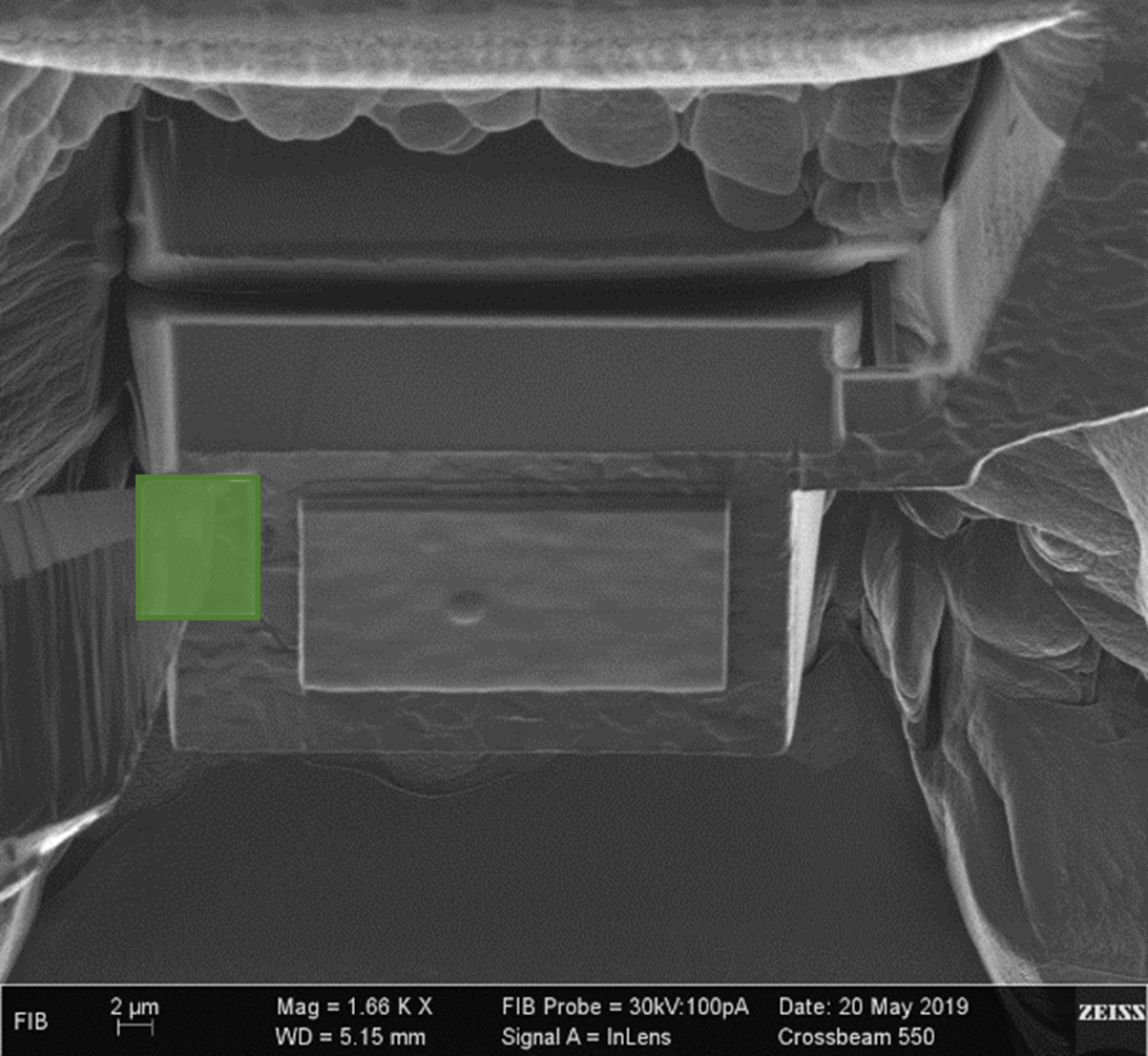
Figure 1. Ion beam micrograph showing the needle in position over the top corner opposite the bridge, with the green box indicating where to deposit the Pt/W
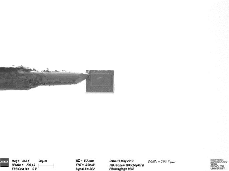
Once the needle is securely attached (I would recommend using lots of Pt/W to deposit, just to make sure), you will need to mill away the bridge to detach the volume from the rest of the sample. This is the moment of truth, if your volume was completely isolated it will easily move away from the sample when you use the needle to remove it. Congratulations, you have successfully removed your volume, now you can fully retract the needle so as not to “bump” the volume off the needle. Figure 2 shows how the volume should look after removal; if the volume appears to be at an angle due then you will do some an extra step later on.
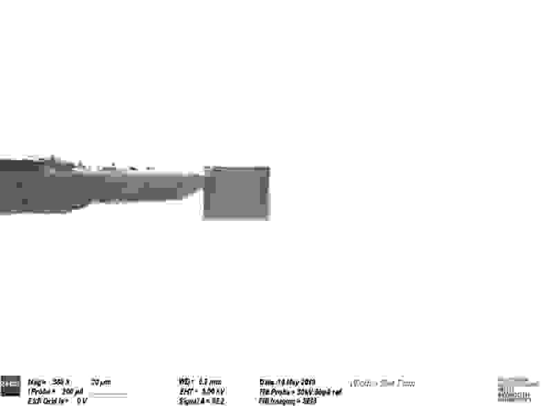
Figure 2. Electron micrograph showing the removed volume on the end of the needle
However, if the volume is still connected underneath the needle will most likely break the “weld” when trying to remove the volume, leaving the volume behind. This is where things start to get tricky and you have realistically have 3 options, 1) reattach the needle in the same/similar place, subsequently followed by re-milling the undercut, but only from 1 side, due to the attachment of the needle; 2) start again if the bridge cut was narrow enough you may be able to re-join the gap using Pt/W and re-mill both undercuts, before reattaching the needle, or 3) start again from the beginning somewhere else. If option 2 is available (i.e. narrow enough cut to re-join with deposition), then I would recommend that, as you can then undercut from both sides. I would always recommend over-milling the undercuts early on to reduce the risk of this happening.
Are we there yet?
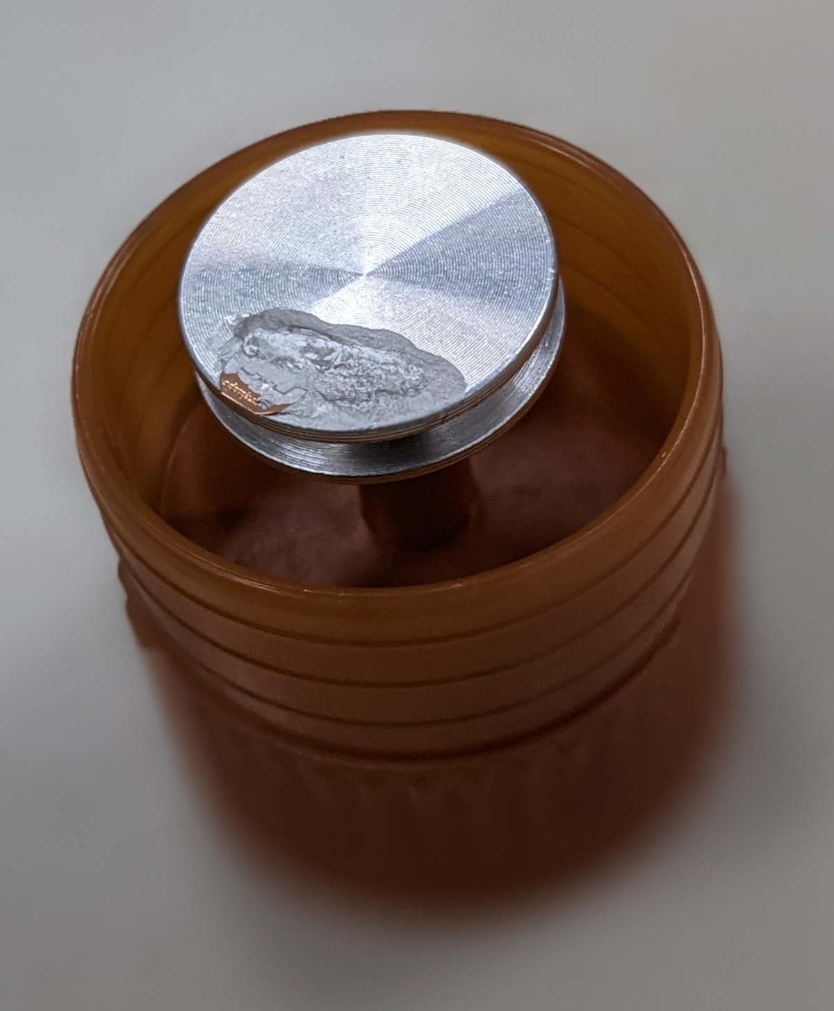
Once the volume has been removed and the needle has been retracted, the sample that the volume will be attached to can be brought into place. I would recommend using our copper Omniprobe TEM half grids, however anything with a flat face will do and is conductive. To mount the grid, I would recommend attaching with silver DAG upside down (with the circle on the right) and backwards, with the flat end slightly overhanging the stub. This will ensure the flat, square face of the grid is face up and the flat back-end of the grid is overhanging to help with attachment and ensure nothing is below the sample. This can be seen in the photo in figure 3.

Figure 3. photograph showing how an Omniprobe grid is mounted for use with 3D EBSD
Before attaching the volume to the grid, the grid will need to be milled slightly to ensure a flat surface between the volume and the grid, which will need to be done at the regular milling angle. I would recommend milling slightly wider than the width of the volume and only a maximum of 1 µm into the grid, otherwise the volume will sit too far into the grid, and you will need to mill away the grid either side. Once done, you will first need to tilt the grid back to 10 0, make grid end face the top of the electron image and then bring in the GIS nozzle. Once the GIS is in place, you can bring the volume back in (but please be careful bringing it in, you don’t want to accidently knock it off after all that hard work like I have before). I would recommend inserting manually and insert above the coincidence in Y (above the grid in the electron view). Once the volume is close, slowly move the volume closer and closer to the face of the polished grid, constantly switching between ion beam and electron beam, to make sure the volume is at the correct height. Once the volume is in contact with the face of the grid (as shown in figure 4), you can attach the volume.
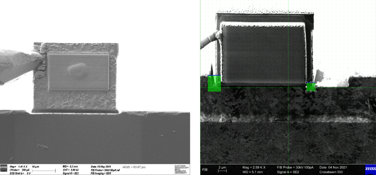
Figure 4. (left) electron micrograph showing the volume is almost in the correct place according to x and y, (right) ion beam micrograph showing the volume being in the correct place according to z and x, with the green boxes showing the initial “weld” points to attach the volume.
Once the volume is attached you can free the needle from the volume and fully retract the needle. I would now recommend tilting the sample to the ion beam angle and deposit Pt/W along the full width of the volume (just to be safe). You will, however, need to retract the GIS before moving the stage, followed by re-inserting back. I would also recommend milling some form of identification next to the volume in the grid, to help with sample identification in the future. Congratulations (again), your sample is now ready for 3D EBSD.
All-in-all
Now you’ve seen how we can prepare a sample for 3D EBSD, whether the area of interest is at the edge of the sample using edge preparation, or whether the area of interest is somewhere else across the sample using chunk lift-out. Both techniques can be ratioed up by using a plasma FIB or even larger volumes by using a laser PFIB system. For the chunk lift-out method I would recommend taking your time and ensuring the volume is completely isolated. This method does have an amount of guesswork involved compared with lamella lift-out, purely because the undercuts can’t be viewed and it’s very difficult to know 100% if the volume is detached underneath.
Some thanks
Majority of this work was carried out during my time at Plymouth Electron Microscopy centre and I also had some very good advice from the Loughborough Materials Characterisation Centre.