In my previous blog post, we looked at preparing a sample for 3D EBSD using the edge preparation method, however that method isn’t suitable for all applications. What if what you want to analyse is in the middle of the sample? You can edge prepare a region of interest (ROI) that isn’t at an edge. This second part of preparing your sample for 3D EBSD will begin to look out doing chunk lift-out.
Let’s increase the difficulty with a chunk lift-out
This technique can be one of the fiddliest (and most infuriating) lift-outs, especially if you have a material that tends to redeposit easily, e.g. sapphire, gilsocarbon, many geological minerals. This technique allows for 3D EBSD to be carried out on any ROI in a sample, which gives it much more flexibility in terms of what can be analysed. However, the ROI does need to be transported from the sample to an edge to allow 3D EBSD to be carried out. Compared to lamella lift-out, this is a bit more difficult, but once it’s out, that’s it, not much else to do.
Chunk isolation
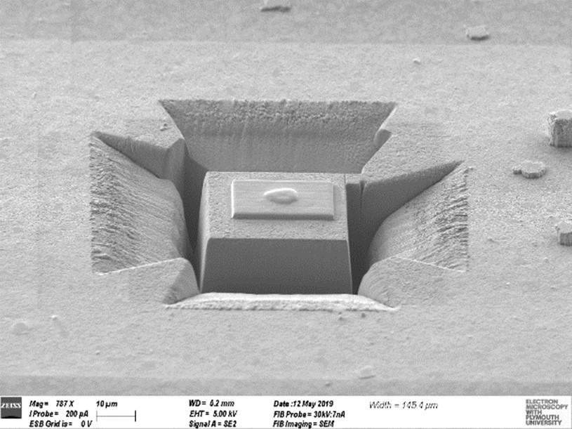
As in my previous post, you will want to start off with depositing a protective layer over the ROI. Once deposited, you will need to begin isolating the volume from the sample. Do this by removing the material around the ROI, while making sure you leave a bridge to connect the volume with the sample. Why this is important will become apparent later, and without it, it makes things very difficult. As shown in figure 1, I would recommend leaving extra space to the side where the manipulator attaches (on the left in my case) and the side that you will attach to the edge (the bottom). This isn’t necessary but makes it a bit easier to get a clean ROI later. I would also recommend using the shapes shown in figure 2, and use the loop milling pattern (with a probe current of ~15-30 nA) to reduce any redeposition and enable viewing the bottom of the cross-section. This should then be followed up by some fine milling with a probe current of ~1-3 nA to get a better polish and make the sides much flatter.
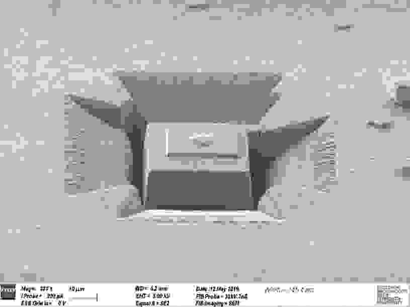
Figure 1. Electron micrograph showing the ROI being isolated with extra space on the left and bottom of the ROI
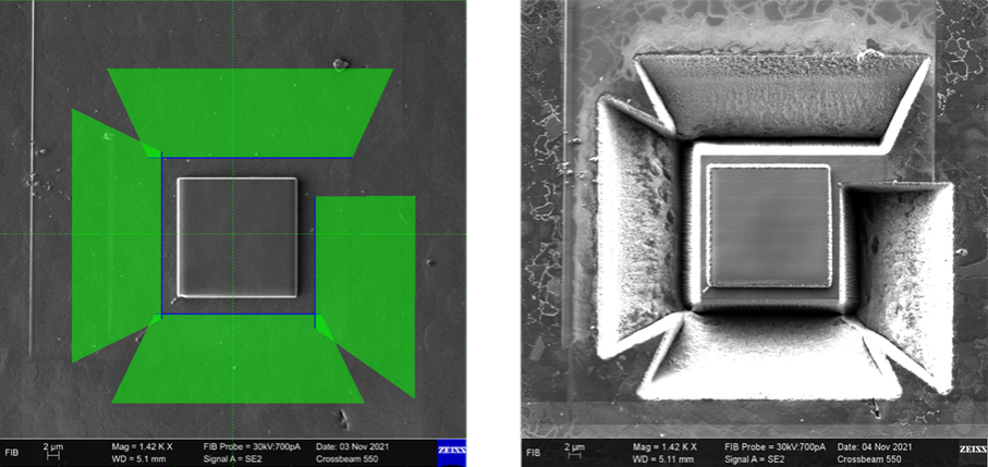
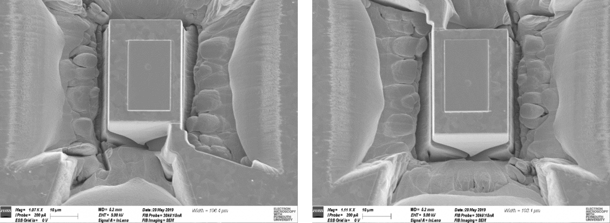
Figure 2. Ion beam micrographs of the ROI before milling (left) and after milling (right), with the right image showing the connecting bridge. The blue line on the green shapes indicates the milling direction and will be the “polished” face, i.e. from outside moving in
The dreaded undercut
Now for the tricky part… removing material below the volume. This is the infuriating part, and what’s worst is that you won’t know whether the volume is completely detached until you try and lift it out. The first step to do is to view the cross-section you need to mill using the ion beam – this is generally done at a stage tilt of 10 0. Once you have the cross-section in view, you can begin to remove material below the ROI (including making the bridge thinner, for easy detachment later), as shown in figure 3. Like with some of the previous millings, you will want to use a loop pattern to reduce redeposition.
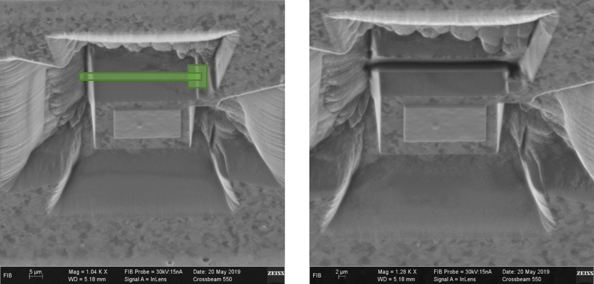
Figure 3. Ion beam micrograph showing before (left) and after (right) milling at 10 0. The left image shows milling boxes for removing material below the ROI and making the bridge thinner. Note, that for removing material below, you should make sure the beam moves from low to high with respect to the surface (top to bottom as you see here) and the opposite for making the bridge thinner.
Now one side has been done, you will need to rotate the stage 180 0 and remove the material below again. Once done, you can at least check the adjacent sides to make sure the cuts intersect each other, as shown in figure 4. Apart from checking the sides, you will just have to hope that the middle isn’t connected (which can be the case a lot of the time, if not milled enough). I recommend using a high dose (~1.5x what you used for side mills in figure 5) and ~4-5 loops.

Figure 4. Electron micrographs showing the two adjacent sides, to check that the undercuts intersect
I think that is a good place to stop for now, in my next post, we will look at lifting the chunk from the sample and attaching to another sample to create a new “edge”, ready for EBSD analysis.
Acknowledgments
I carried out this development at Plymouth Electron Microscopy Centre while I worked there before making the move to Oxford Instruments and I would like to thank Loughborough University for giving me advice on this method when I first began working on it.