I get asked a lot on what’s the best way to prepare a sample for 3D electron backscatter diffraction (EBSD) and it really depends on where on the sample you want to carry out 3D EBSD. Running EBSD in 3D is very different from just carrying out a normal 3D run. The main difference being that 3D EBSD can only be carried out at the edge of the sample, as there is no way to carry out EBSD on a cross-section in the middle of a sample. However, there is a way to get around this without having to machine your sample down (which I’ve heard someone recommend before).
There are 2 ways to prepare a sample for 3D EBSD, one of which requires the sample to be flat/polished on 2 faces, such as the sample shown below in figure 1. This would be the case if your sample is either, a) homogeneous and you can analyse the grain structure at the edge and it still be representative, or b) your region of interest (ROI) is at/near the edge. The second way is to lift-out a small volume from an ROI on the sample and attach that volume to edge of something else. The former is much faster and easier to prepare but the latter gives you much more flexibility.
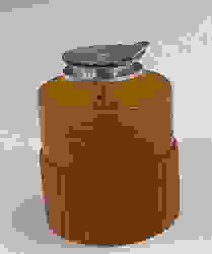
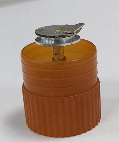
Figure 1. Photograph of a sample with 2 polished faces, with one face being EBSD ready and the other being flat
Starting off “easy”, with edge preparation
Like with running a normal 3D run, you should probably start off with depositing some Pt (or any other material that use for protection) on the non-EBSD polished face, to protect the top surface of the ROI that you’re wanting to analyse. To save time, you should deposit the protective layer as close as possible to the edge. The aim for preparing a volume for 3D EBSD (or even normal 3D) is to isolate the volume from the sample, effectively creating a small cube, with the material around it being removed. Technically you don’t have to do this, but if you don’t, you will have to set-up your 3D milling box to be much, much bigger than your ROI.
Once you have your protective layer over your ROI, you will firstly want to remove the material from either side; this is to remove/minimise the chance of causing shadowing on the phosphor screen as the 3D run progresses (however, the shadow mask feature in AZtec works wonders on this issue, but I still think it’s good to remove as much material as possible). Fortunately, there is a relatively quick way to go about this, as you don’t need to use rectangle shapes to mill. What you can do instead is use right-angled triangles, as shown in figure 2 below, this enables a 45 0 cut from the rear of the ROI to face of the sample. I would mill these large shapes with using a relatively large probe current of at least 30 nA, just to speed things up, and then “polish” the sides up to the ROI with a smaller probe current of ~1-3 nA.).
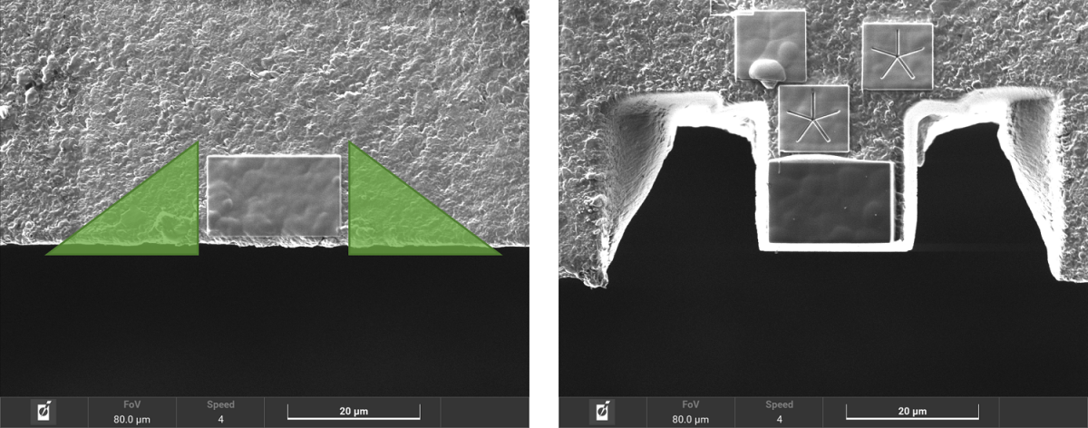
Figure 2. Ion beam micrograph showing the before (left) and after (right) milling of the side trenches
Now the sides have been removed, you will want to do the same below the ROI, for the same reasons as before – remove shadowing and speed up the run by not having to mill as much during the run. To do this, you will want to rotate the stage 180 0 so the EBSD face is now facing towards the ion beam (this will also be a similar position to EBSD acquisition in a dynamic FIB system). I would use a plain box mill while using a loop-mill pattern to reduce any redeposition, but you could use a step mill to save time.

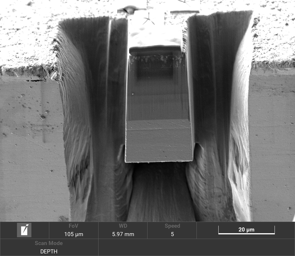
Figure 3. Electron micrograph showing the isolated volume
Congratulations! Your ROI has now been isolated and you can efficiently carry out 3D EBSD on the edge of your sample, much like what is shown in figure 3.