Inclusions – solids, liquids, or gases trapped within minerals during crystallization – are essential tools in geology. They act as natural “time capsules,” providing direct evidence of Earth’s history, geological processes, and environmental conditions such as pressure, temperature, and chemical composition. While correlative techniques such as LA‑ICP‑MS, SIMS, or FIB‑SEM‑EDS offer highly sensitive and chemically detailed analyses of inclusions, truly non‑destructive characterization methods that preserve both the trapped phases and their host minerals are largely limited to light‑ or X‑ray‑transmitting approaches, including Raman spectroscopy, infrared spectroscopy, micro‑CT, and heating–cooling stages. Among these non‑destructive techniques, Raman spectroscopy and Raman imaging uniquely provide mineralogical and structural/molecular information at spatial resolutions suitable for detailed inclusion characterization – a capability that is particularly crucial for geobarometry and for detecting minute phase or stress variations within and around inclusions [1,2].
The witec360 microscopy platform offers a multitude of optical features to detect and characterize inclusions. A typical workflow to study inclusion would be:
Step 1: Finding inclusions
Searching for inclusions requires a high‑resolution optical microscope equipped with multiple illumination modes, including reflected and transmitted light in dark- and brightfield, as well as capabilities to include white‑light polarization and Köhler-illumination control. Figure 1a shows a natural diamond imaged in transmitted bright-field white light using a 20x air objective, revealing at least four inclusions of varying sizes, all located several micrometers beneath the surface. Because all six objectives on the microscope turret are calibrated and offset‑corrected, the high‑resolution 100x objective can be positioned on the same area of interest with a single mouse click (Fig. 1b). To image the entire inclusion (A) at high resolution, the stitching function combined with focus stacking in the SUITE 7 software is employed.
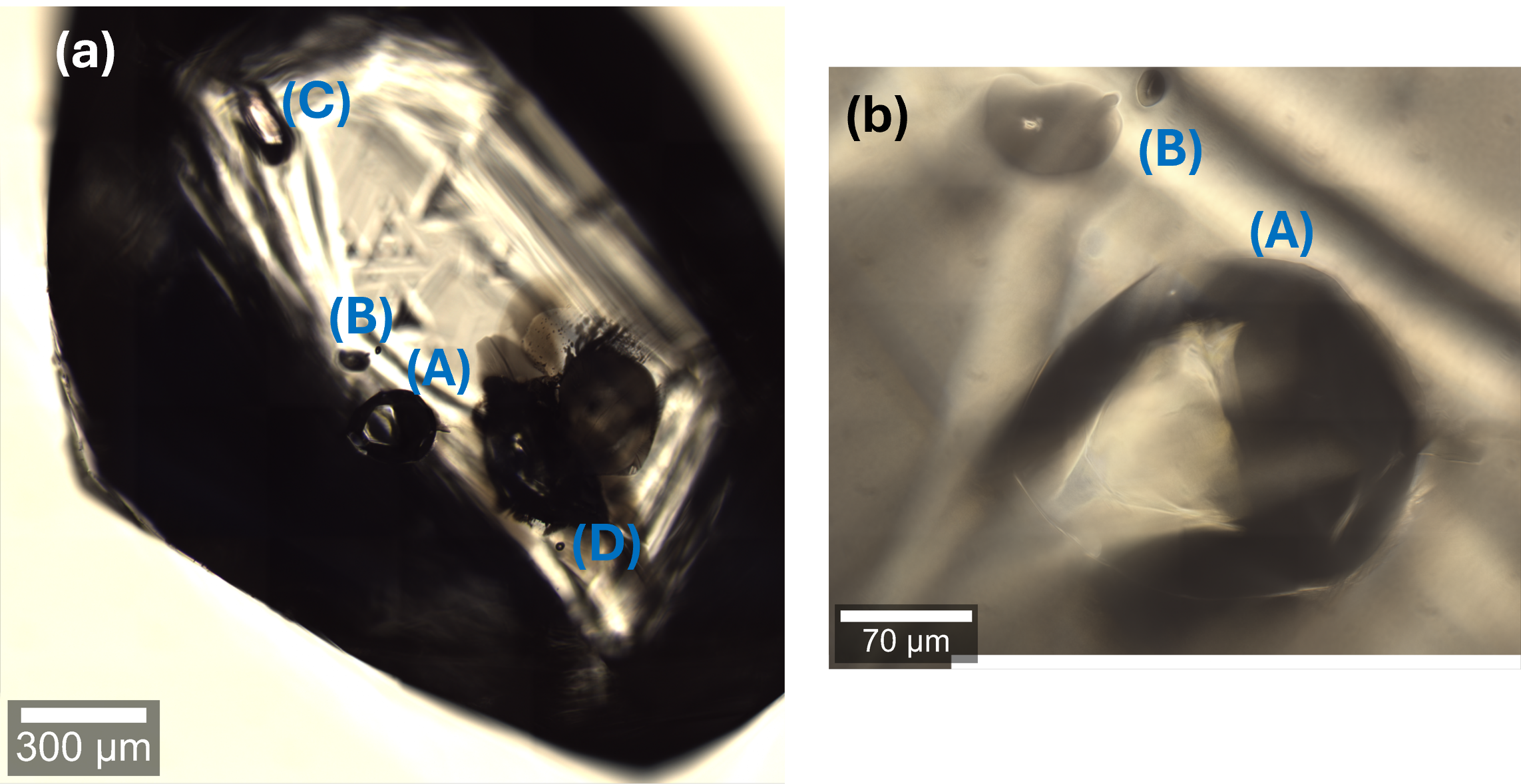
Fig. 1: Optical localization of inclusions within diamonds: Overview image of diamond in transmitted light using a 20x/0.5 air objective (a) and high-resolution transmitted light image of inclusion (A) using a 100x/0.9 air objective (b).
Step 2: Chemical identification
The precise depth position of the inclusion can be determined by performing a confocal Raman line scan along the z‑axis. Figure 2a shows a representative Raman spectrum containing the characteristic Raman bands of forsterite (indicated in blue) and diamond (indicated in red). The line scan shown in Figure 2b consists of 40 Raman spectra acquired over a z‑range of 100 µm, revealing the corresponding intensity variations of the diamond (red) and forsterite (blue) Raman bands. For chemical identification, the fully integrated TrueMatch software package provides an ideal tool. In this example, the chemical composition of the inclusion was determined using reference spectra from the free RRUFF database [3].
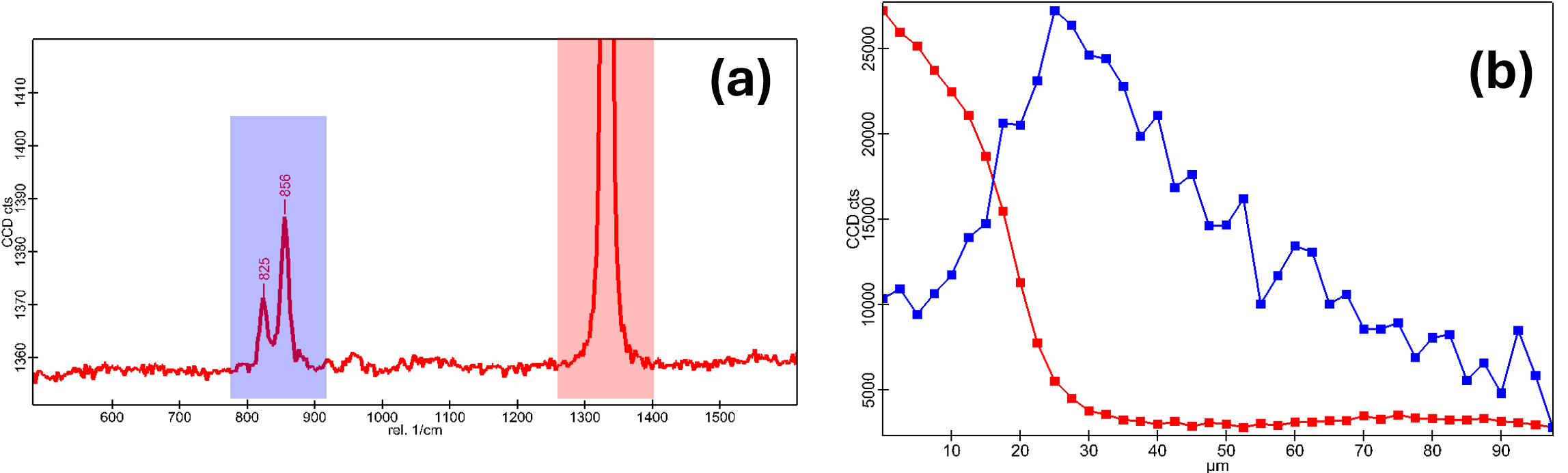
Fig. 2: Mixed Raman spectrum of diamond (red) and forsterite (blue) acquired from inclusion (A), and depth profile showing the intensities of the two materials acquired during a z-scan.
Step 3: Detailed analysis of the inclusions
With the depth position determined, the features within the inclusion and the surrounding host material can now be characterized. As already shown in Figure 2, inclusion (A) consists of forsterite. Inclusion (C) was localized using the same procedure described above and subsequently imaged by acquiring a two‑dimensional array of Raman spectra. The region of interest is selected directly on the video image (Fig. 3a) using a simple mouse drag. For this Raman imaging experiment, the acquisition parameters were chosen such that a full Raman spectrum is recorded at every micrometer step. Owing to the high confocality of the Raman microscope, it is possible to characterize a thin optical section of the inclusion with high spatial precision.
Step 4: Data evaluation
Without prior knowledge of the sample, the two‑dimensional array of Raman spectra (hyperspectral image) can be evaluated using a guided software workflow. First, the spectra undergo cosmic‑ray removal and background correction, followed by a analysis of the 2D spectral dataset (TrueComponent analysis). This procedure yields a set of extracted components, each represented by an individual image and its corresponding Raman spectrum. A color‑coded Raman image is then generated (Fig. 3b), in which each color corresponds to the color of the respective Raman spectrum shown in Figure 3c.
In this case, the inclusion consists of pyrope (green) surrounded by a distinct fluid rim (blue) at the interface with the diamond host (red). According to the literature [1,2], such fluid rims, which exhibit broad Raman bands from 660 to 800 cm⁻¹ characteristic of non‑crystalline material, are associated with Si₂O(OH)₆ dimers and Si(OH)₄ monomers. These species provide valuable insights into the formation history and physicochemical conditions under which the inclusion originated.
This study demonstrates how non‑destructive Raman spectroscopy and imaging provide essential mineralogical and structural insights into geological inclusions, which are critical for reconstructing Earth’s formation conditions and advancing geoscientific research. By integrating high‑resolution optical imaging, confocal Raman depth profiling, and hyperspectral data evaluation, the witec360 platform enables precise localization, chemical identification, and detailed characterization of inclusions and their surrounding phases. This workflow establishes witec360 as an ideal and comprehensive tool for the scientific community, delivering the resolution, analytical depth, and software integration necessary to uncover the complex histories preserved within mineral inclusions.
[1] Suzette Timmerman et al, Earth Planet. Sci. Lett. 671 (2025) 119635.
[2] Nimis Paolo et al., Lithos, 260 (2016) 384-389.
[3] RRUFF Raman database of minerals (www.rruff.info)
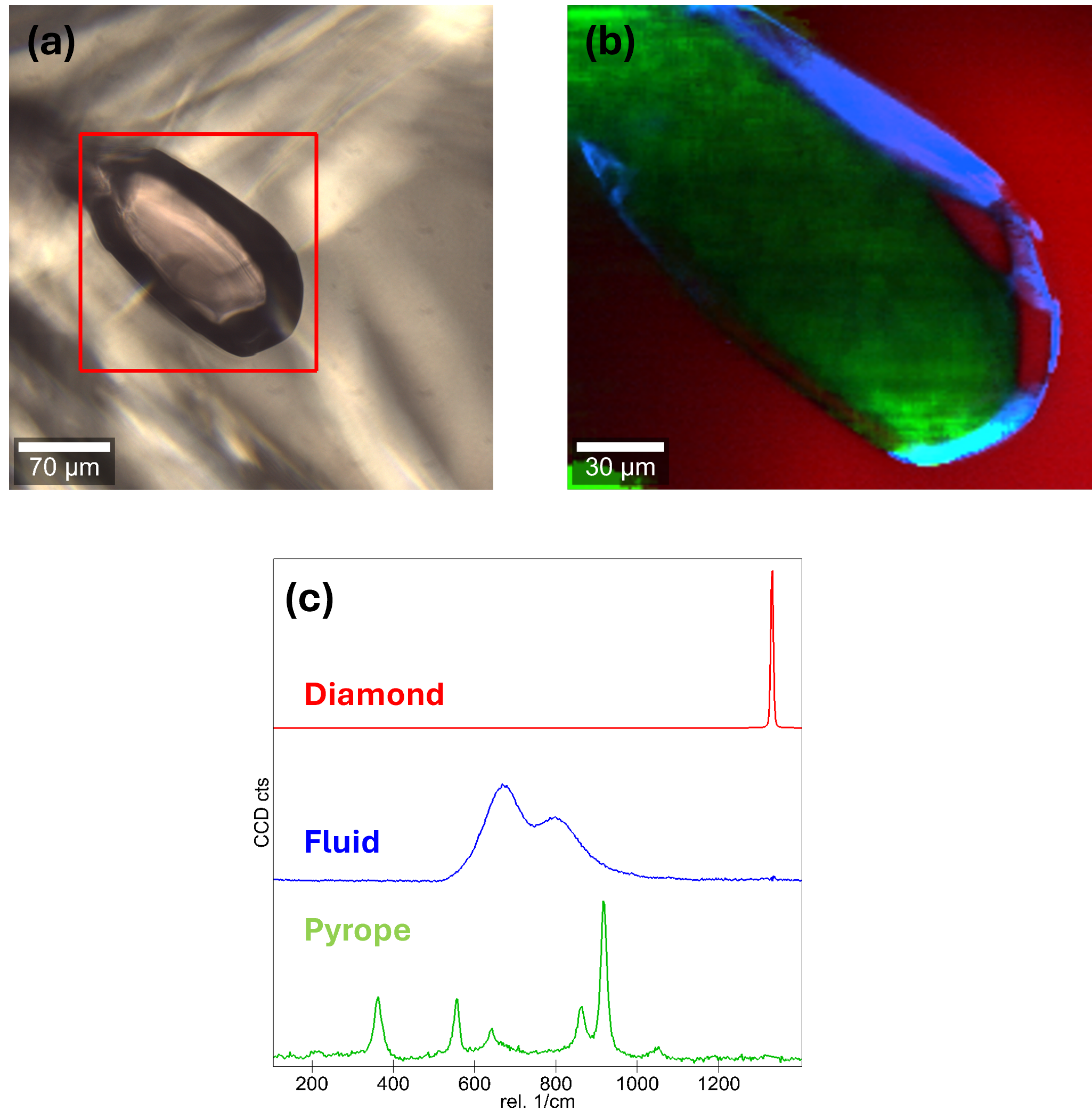
Fig. 3: Transmitted white light image of inclusion (B), the red frame marks the area for the Raman image (a), color-coded Raman image of the inclusion (b) and corresponding Raman spectra (c).

