Published: 10 Feb 2021 · Last updated: 30 Jul 2025
sCMOS based cameras can provide a much lower noise floor than typical CCD based cameras. A low noise floor means that the camera can detect signals that would otherwise have remained hidden within the noise background which helps to produce a high-fidelity image. A low noise floor also allows for the widest possible dynamic range. One of the main types of noise that makes up this noise floor comes from “Read Noise”.
What is Read Noise?
Read noise is the noise that is produced during the transfer of charge from the pixels to the camera. It is a measurement of the amount of noise that the camera system's electronics produce by default. This noise is produced as the circuitry of the camera processes and amplifies the charge contained in the pixels. Since read noise directly affects the signal-to-noise ratio and the overall quality of the image, it is essential to comprehend and minimize it in order to achieve high-quality imaging. The camera can take clearer, more detailed photos by lowering read noise, especially when working with weak signals or in low light. Read noise is created within the camera electronics during the readout process as the electrons are subjected to the analog to digital conversion, amplification and processing steps that enable an image to be produced. In this technical note we look at some of the important aspects of read noise for sCMOS sensors.
Readout Noise in sCMOS Sensors
In the case of CCD sensors, all the pixels in a sensor pass through a common architecture and are essentially subject to the same sources of noise during the readout process. Therefore, the read noise of a CCD sensor can be described by a single readout noise value.
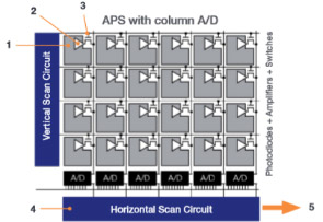
The readout process for sCMOS however is different, sCMOS sensors are often referred to as “Active Pixel Sensors” (APS) since each pixel has its own amplifier circuit (Figure 1). The overall process is outlined below:
Figure 1: The main components of a sCMOS sensor.
Photons hit the sensor and generate charge (electrons).
The photo-generated charge is converted to an analog voltage for each pixel amplifier.
These pixel voltages are transferred to the column bus via a row select signal.
The analog voltages are then converted to digital signals via columns of analog to digital (A/D) converters.
The final digitized signals are then read out sequentially at a pixel readout speed which normally can be set at different speeds.
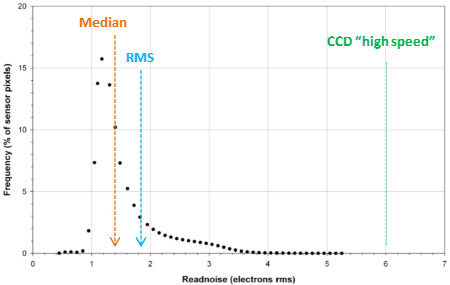
Since every pixel has its own amplifier circuit for converting the electrons to a voltage signal, each pixel will have a slightly different read noise value. So, the read noise of a sCMOS sensor will therefore have a noise distribution (Figure 2).
Figure 2: A representation of the read noise distribution for a sCMOS Sensor.
For sCMOS cameras the distribution of readout noise is commonly described as the median value of the distribution. An example of an sCMOS read noise distribution is illustrated below.
In this example the median value is 1.2. This simply means that 50% of the pixels will have a noise less than 1.2 e- and 50% of pixels will have a noise above 1.2 e-. Due to the asymmetric profile of the distribution curve there will only be a small number of the higher noise pixels as the distribution tails off. It must be noted that a CCD camera reading out at high speed would have 100% of the pixels with a read noise in the region of 6-10 e- rms.
The rms value – which is the root mean square value of all pixels, may also be used to describe the noise distribution of sCMOS cameras. This value is used for CCD cameras but is less commonly used for sCMOS cameras. The rms value is more suitable for characterising the noise of cameras in signal to noise ratio calculations. The rms noise figure will typically be higher than the median value for example, the Zyla 4.2 PLUS has a median noise of 1.2 and the rms noise of 1.6 e- (for the same settings).
What factors affect Read Noise?
Read noise is inherent to the readout process of the sensor itself but cameras from different manufacturers that are based around the same sensor can have some significant differences in how the sensor has been implemented. Therefore, the noise performance of the different camera models can be different despite using the same sensor.
sCMOS cameras are remarkably flexible imaging devices and have several settings that allow them to be optimised for different applications such as high speed, or for high dynamic range imaging. Different cameras will have different behaviours as settings are adjusted and this also includes how read noise is affected. Therefore, you need to look at the read noise of the camera for the settings you will be imaging at. This may not be immediately visible in some camera specification sheets so you may need to read any footnotes provided. For some cameras, read noise will be higher at faster readout speeds than at lower speed modes (Table 1).
Camera
Mode
“High Dynamic Range” (16-bit)
“Fastest Frame Rate” (12-bit)
Zyla 4.2 PLUS
0.9
1.1 (↑0.2)
Neo 5.5
1.2
1.45 (↑0.25)
Marana4.2B-11/Sona 4.2B-11
1.6
1.6 (-)
Table 1: Examples of read noise (e-, median) in sCMOS cameras under different modes.
In Table 1 we can see that Zyla 4.2 PLUS and Neo 5.5 both show an increase in read noise at the higher readout speeds – though nowhere near the increase that would be found for a CCD based camera. In contrast, the Marana and Sona 4.2B-11 show no increase in read noise as the speed is increased.
Rolling and Global Shutter: Many sCMOS cameras function in what is termed Rolling Shutter mode. Some models such as the Zyla and Neo 5.5 also can operate in Global Shutter mode.
Camera
Mode
“High Dynamic Range” (16-bit)
“Fastest Frame Rate” (12-bit)
Neo and Zyla 5.5
1.2 [1.7]
2.4 [2.7]
Table 2: Comparison of read noise between Rolling Shutter and Global Shutter operation (e-, median [rms]) in sCMOS cameras under different modes.
Rolling Shutter allows for a lower read noise than global shutter as well as higher frame rates. It is for this reason that most sCMOS cameras are of the Rolling Shutter type. However, Global Shutter does provide advantages for certain high-speed applications. To find out more about operation in rolling shutter and global shutter, click here to view the Rolling and Global Exposure article in our learning centre.
Spurious Noise Filter: Since the background noise of sCMOS cameras is so low, the small percentage of higher noise pixels can become an aesthetic issue. Enabling the Spurious Noise filter can actively correct for these pixels in the image by replacing the high value pixels with the mean value of the surrounding pixels. The filter can be disabled if data acquisition experiments are required.
Summary
Read noise is one of the main sources of noise in an imaging camera for relatively short exposures
Low read noise is desirable as it allows the camera to detect low level signals and attain a high dynamic range
The read noise of sCMOS camera is a noise distribution and is normally given as in e-, as a median value
Check the specification sheet, including any related footnotes to ensure that the read noise quoted applies to your intended mode of operation
Check the performance sheet supplied with your camera for the values specific to your individual camera * Further related technical information is available in the Andor Learning Centre