In recent research on quantum communication parametric down-conversion (PDC) in χ(2)-nonlinear crystals play a major role for the generation of photon pairs (see e.g. [1], [2], [3]). In particular, the addressing of atomic transitions for quantum memory applications [4], [5] requires a precise knowledge of the spectral emission characteristics of PDC sources. With the integrability of different functionalities on one chip, promising pair sources rely on sophisticated wave guiding structures providing nonlinear conversion efficiencies, which are several orders of magnitude higher than those of any bulk crystal [6].
Introduction
The Z-cut Lithium Niobate (LN) is a well-understood material with high nonlinearity properties. It can allow the fabrication of high quality guides which can confine wave propagation over several centimeters, whereas high pump intensity in bulk crystals can only be achieved over much shorter distance.
In this work, a Research team at the University of Paderborn spectrally characterized a nondegenerate Type-I PDC source in Titanium-indiffused periodically poled Lithium Niobate (Ti:PPLN), where a pump photon at 532 nm polarized along the extraordinary crystal axis decays into two photons with the same polarization at around 800 and 1575 nm respectively.
Figure 1 shows the schematic of the source. It consists of a Ti:PPLN waveguide, which was periodically poled with a periodicity of around 6.8 μm to achieve so-called quasi-phasematching.

Figure 1: Schematic of the Ti:PPLN photon-pair source
Parametric down-conversion
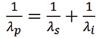
Parametric down-conversion is a three-wave-mixing process, where pump photons of a specific energy, represented by their wavelength λp, can couple to a vacuum quantum state and decay into two daughter photons, commonly labeled signal (s) and idler (i). For this process, energy conservation has to be fulfilled:
Furthermore the conservation of momentum must hold:
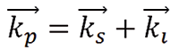
where the different  represent the wave vectors of the respective photons. This equation is usually called phasematching condition. In bulk χ(2) nonlinear and birefringent optical materials, an angular degree of freedom is given with respect to the phasematching condition, so that specific combinations of signal and idler wavelengths can be achieved by tuning this angle.
In contrast, waveguides in nonlinear materials can confine light over longer distances due to total reflection of light at the waveguide boundaries, implying a restriction to only one translation degree of freedom, i.e. the propagation direction of the interacting photons. This also implies that we are limited to only one translatory degree of freedom, namely the propagation direction of the interacting photons. The wave vectors can be replaced by scalars of effective wave numbers for the individual guided mode:
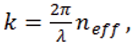
where λ represents the photon wavelength and neff is the effective refractive index. Due to chromatic dispersion, a phase-mismatch occurs in waveguided PDC processes:
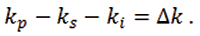
Here the additional paramater Δk expresses the phase mismatch in terms of additional wave number. To compensate for this, a common technique called periodically poling, is employed. The spontaneous polarization inversion in the crystallographic medium introduces an additional rating vector, which modifies the phase-matching condition of equation (ii). The required poling period ΛG is given by
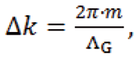
where m is an odd integer representing the order of the quasi-phasematching. Together with the conservation of energy given by Equation (i), the conservation of momentum defines the possible wavelength combinations for a given poling period in waveguidebased PDC processes. For a given pump wavelength and poling period, the wavelength combination of signal and idler can be determined. Tuning those wavelength can be accomplished by varying the temperature of the device.
This is due to the temperature dependence of the effective refractive indices. For applications requiring stable PDC sources, it is therefore important to understand and characterize the spectral shift with device temperature.
Waveguide Technology
For these experiments waveguides with a fixed width of 7 µm were manufactured. The polishing periods were varied between 6.71 and 6.91 µm across the device width. The waveguides were fabricated by Titanium-indiffusion at 1060°C over 8.5 hours. To achieve the best possible coupling of light into and out of the waveguides, the end-facets were polished perpendicularly to the propagation direction. To improve the overall conversion efficiency of the device, Krapick’s team developed and deposited dielectric coatings (EFC) for optimum incoupling of the pump wavelength. The best possible outcoupling of signal and idler wavelengths, including the reflection of the pump, was achieved by a 16-layer coating at the waveguide output.
Experimental Setup
The setup used for the nonlinear optical characterization is shown in Figure 2. It consists of three different sections:
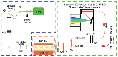
Figure 2: Experimental setup for spectral PDC measurements; NDF: neutral density filters, BL: beam blocker, HWP: half-wave plate, RG715: customized absorptive filter, DM: dichroic mirror, NF: needle filter, BPF: band-pass filter, FC: fiber coupling stages, MMF: multi-mode fiber. SMF: single-mode fiber
A prism-based beam cleaning ensures that only the pump wavelength is launched into our device and variable attenuators in combination with neutral density filters are used to control the optical pump power. The TM polarization is set by an additional half-waveplate positioned before to the AR-coated coupling lens.
The sample alignment setup consists of a home-built high-precision five-axis stage, while the temperature can be changed or stabilized at sufficiently high levels to prevent so called photorefractive damage (T>140°C), which is the light-induced, highly dynamic change of refractive indices mediated by the nonlinear electro-optic effect.
The team chose a flexible free-space configuration including several (partially home-made) spectral filters and absorbers for high transmission of the signal and idle beams.
A dichroic mirror splits the PDC output into signal and idler arms, with the signal arm being coupled to a multimode fiber. The PDC spectral characterization is done by an Andor iKon-M DU934P-BR-DD CCD detector coupled to a Shamrock SR303i-A-SIL with silver-coated optics for enhanced efficiency in the near infrared, and an XY adjustable fiber. The Shamrock spectrograph triple grating turret and entrance slit were adjusted remotely through Andor Solis software.
A 1200 l/mm grating blazed at 500 nm was used in conjunction with a 10 μm wide slit to achieve the highest possible resolution. The CCD acquisition mode was set to full vertical binning operation and kinetic series. A readout speed of 50 kHz and a pre-amplifier of 4 were chosen to obtain the best signal to noise ratio performance. The exposure time was chosen to be 0.025 s.
Results and Discussion
The nonlinear characteristics of the PDC source have been determined by measuring the spectral behavior with changing device temperature or with different poling periods. Figure 3 (overleaf) shows the coarse and fine wavelength tunability associated with poling period and temperature variation respectively. A strong dependence of the PDC signal emission on the poling period and the position on the device was identified. The higher central peaks indicate stronger nonlinear interaction efficiency in the central parts of the PDC device. The team explained this phenomena by the presence of a more homogeneous periodic poling pattern in this section, while in the edge regions the poling slightly suffers from so called over- or underpoling. This reduces the effective interaction length of the PDC process.
Figure 3 shows the possibility to precisely control the generated wavelengths by tuning the device temperature. The Andor detection system provided the high sensitivity necessary for these measurements, while also exhibiting negligible optical etaloning. The graphs in Figures 3 and 4 show no significant impact on the spectral profile of the optical interferences within the sensor’s Fabry-Pérot interferometer-like structure. For the high pre-amplifier gain chosen, the base level was around 300 counts.
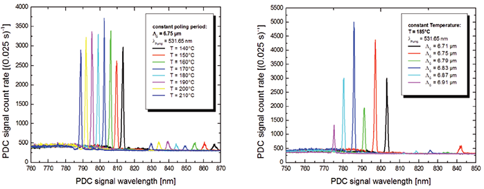
Figure 3: Tunability of the PDC signal wavelength with the crystal‘s poling period (left) and temperature (right)
Note that there is only one sidepeak per spectrum, indicating a higher order spatial waveguide mode excitation around 45 nm shifted on longer wavelengths. This represents an excellent waveguide homogeneity and good coupling of the pump light to the fundamental spatial waveguide mode.
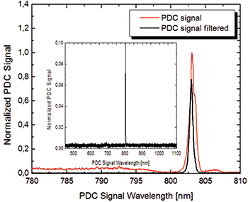
Figure 4: Unfiltered (red) and needle-filtered PDC signal (black), inset: background spectral characteristics
In preparation of later experiments, a dielectric needle filter was implemented to the signal arm. With this, the spectral characteristics of the PDC source in the Silicon detection band exhibited no additional photon signal exceeding 0.6% of the maximum PDC signal level.
The needle filter has a FWHM bandwidth of <0.5 nm and a maximum classical transmission of TNF,s=0.78 as shown in Figure 4 and its inset. The large wavelength range shown in the inset graph was obtained with the software-controlled ‘step and glue’ mode of the spectrograph. This allowed broadband spectral acquisition at higher resolution.
Conclusion
The team at University of Paderborn spectrally characterized a waveguide-based type-I PDC source in Titanium-indiffused waveguides in periodically poled Lithium Niobate with a single-photon sensitive high-resolution spectrograph and was able to verify its excellent performance with respect to sample homogeneity and tunability.
References
- A. Martin, O. Alibart, M. P. De Micheli, D. B. Ostrowsky, and S. Tanzilli. A quantum relay chip based on telecommunication integrated optics technology. New Journal of Physics, 14(2):025002, 2012.
- A. Christ, C. Lupo, K. Laiho, A. Eckstein, K. N. Cassemiro, and C.Silberhorn. Multimode ultrafast broadband information coding: State generation, characterization and loss evaluation. In CLEO/ Europe and EQEC 2011 Conference Digest, page EA12, Optical Society of America, 2011.
- N. Sangouard, B. Sanguinetti, N. Curtz, N. Gisin, R. Thew, and H. Zbinden. Faithful entanglement swapping based on sum-frequency generation. Phys. Rev. Lett., 106(12):120403, March 2011.
- C. Clausen, I. Usmani, F. Bussires, N. Sangouard, M. Afzelius, H. de Riedmatten, and N. Gisin. Quantum storage of photonic entanglement in a crystal. Nature, 469:508-511, 2011.
- E. Saglamyurek, N. Sinclair, J. Jin, J. A. Slater, D. Oblak, F. Bussires, M. George, R. Ricken, W. Sohler, and W. Tittel, Broadband waveguide quantum memory for entangled photons. Nature, 469:512-515, 2011.
- M. Fiorentino, S. M. Spillane, R. G. Beausoleil, T. D. Roberts, P. Battle, and M. W. Munro. Spontaneous parametric downconversion in periodically poled KTP waveguides and bulk crystals. Opt. Express, 15(12):7479-7488, Jun 2007.

