Key Message: BEX enables failure analysis where shadowing inhibits EDS—allowing compositional analysis of pristine fracture surfaces that hold vital root cause evidence.
Turbocharger turbine blades operate under extreme mechanical and thermal loading, experiencing centrifugal stresses exceeding 600 MPa and temperatures beyond 1000 °C during rapid acceleration [1,2]. To prevent plastic deformation, cracking, or blade loss under these conditions, turbine materials must combine high tensile strength with strong resistance to fatigue and time‑dependent creep. These requirements commonly drive the use of nickel‑based superalloys [1], which retain strength and microstructural stability at temperatures where many materials soften, oxidise, or creep unacceptably [1].
However, when component failure occurs prior to the end of expected service life, timely and systematic failure analysis is essential to establish the root cause, prevent recurrence, and protect overall fleet reliability.
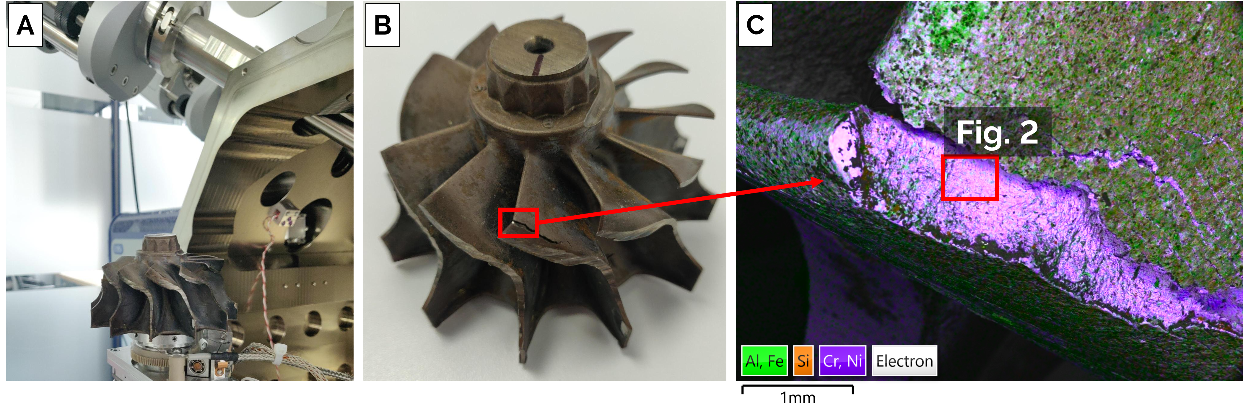
Figure 1- A) Image of bulk turbine wheel in-situ on the SEM stage. B) Image of failed turbo blade in-situ on turbine wheel. C) Low magnification BEX image displaying stress fracture of the Ni-Cr alloy with surficial Fe-Al-Si coating.
This case study presents an alternative approach for the root cause analysis of a failed turbocharger blade. Our investigation uses backscattered electron and X‑ray (BEX) detection in the scanning electron microscope (SEM) to produce high‑quality elemental maps where conventional EDS is compromised by shadowing from large, uneven sample surfaces (Fig.1). Positioned beneath the pole piece, BEX provides a “bird’s‑eye view” geometry that reduces shadowing across highly undulating fracture surfaces. This enables bulk analysis of the failed component with no preparation and without modifying the sample (Fig.1), preserving critical evidence while reducing analysis time and preparation‑related uncertainty.
BEX-Enabled Root Cause Analysis
Visual examination and secondary electron SEM imaging (Figs. 1B & 2C) indicate that the observed fracture morphology is consistent with surface‑initiated fatigue cracking, followed by stable crack propagation under cyclic loading. The crack location and propagation characteristics are typical of turbine blades exposed to repeated thermo‑mechanical loading, where localized stress concentrations promote progressive fatigue damage accumulation. In the present case, however, failure occurred significantly prior to the expected service life, indicating that additional contributing factors not obvious from visual inspection may have weakened the components performance.
The intact turbocharger was therefore examined directly in the SEM and analysed at 20 kV accelerating voltage, 5 nA probe current, and a 25 mm working distance (selected to accommodate the pronounced surface topography of the component, Fig. 1A). Imaging was performed using both the Unity BEX detector and an Ultim Max ¥ 170 energy‑dispersive X‑ray (EDS) detector.
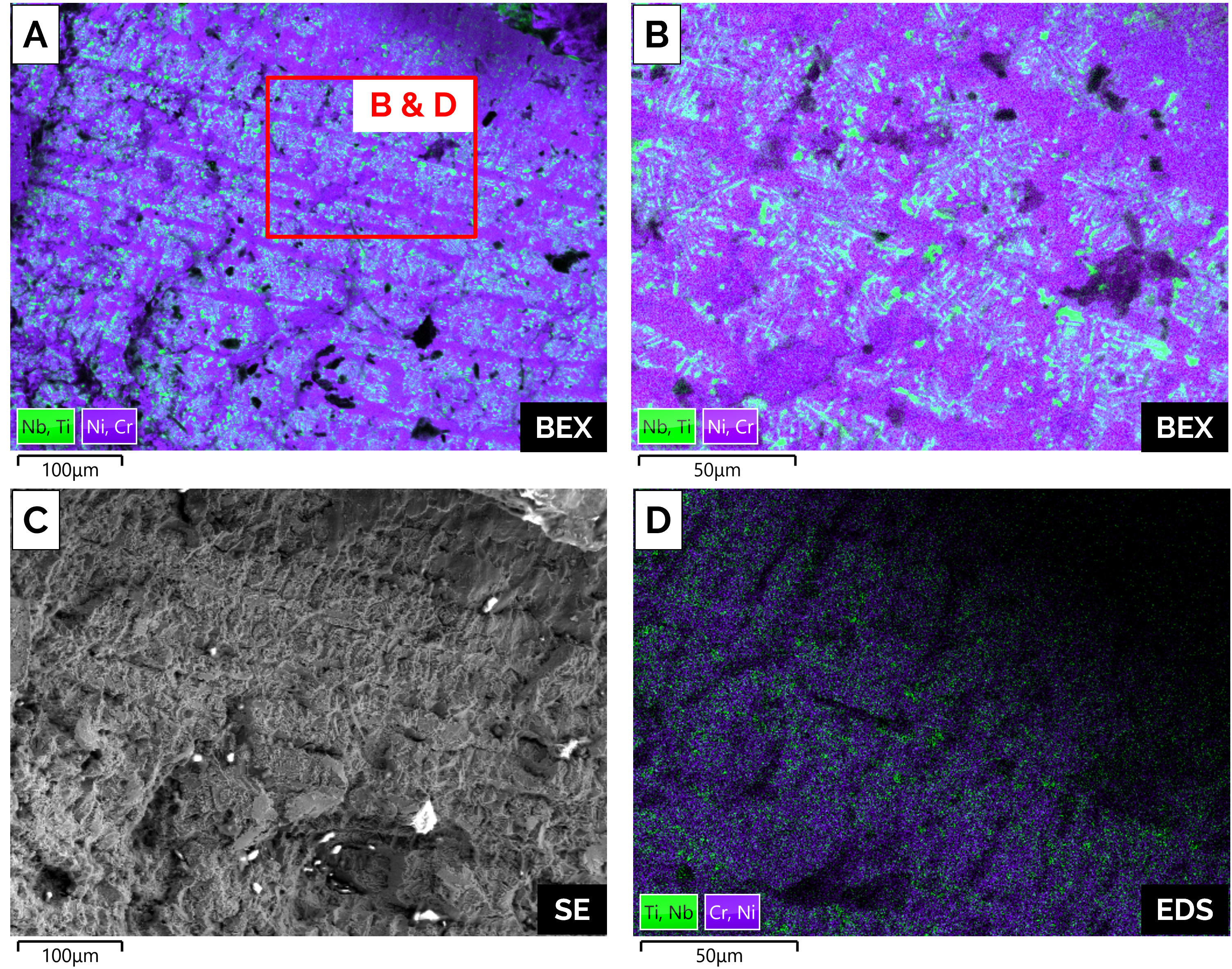
Figure 2- A) BEX image of fracture surface collected at 500 X magnification. Segregation on the order of 10’s µm is clearly visible. B) BEX Image of fracture surface collected at 1500 X magnification reveals assimilation of sub-micron Nb-Ti inclusions. C) Secondary electron image of fracture surface, note apparent stratification correlates with elemental segregation.
BEX images acquired from the fracture surface at 500× and 1500× magnification (Figs. 2A and 2B) reveal pronounced compositional contrast across the fracture surface, consistent with inhomogeneous elemental distribution of Ti-Nb. This artefact is manifested in the stratified fracture morphology observed in the corresponding secondary electron image (Fig. 2C).
Simultaneously acquired EDS data from the same region (Fig. 2D) exhibits pronounced shadowing and reduced signal intensity, preventing confident interpretation of the underlying microstructural features.
While Nb- and Ti-rich inclusions are an expected feature in nickel-based superalloys, this example displays incomplete homogenisation of the brittle Nb leaves phase [3,4]. Such microstructure leads to permanent weak points in the blades structure [3,4] , acting as a site of fracture initiation and propagation and could be the cause of premature component failure.
Conclusion: BEX Creates New Possibilities for Failure Analysis on Automotive Components
Failure analysis of unprepared components presents practical limitations for conventional SEM‑EDS techniques due to component size and pronounced surface topography. These conditions restrict, or even inhibit, detector signal and reduce confidence in compositional interpretation obtained from well preserved components. This example demonstrates how BEX enables SEM‑based failure analysis of large, irregular components without time-consuming sample preparation, preserving critical evidence that conventional SEM‑EDS workflows often disturb or remove.
References
- Dolton (2006): HTi Magazine, Cummins Turbo Tech, Ed. 7, 7-8.
- Sellers (2018): Proc. 65th ICI Tech. Conf., Investment Casting Inst.
- Evangeline et al. (2020): Arab. J. Sci. Eng., 45, 9685–9698
- Zhang et al. (2022): Compos. Part B: Eng., 239, 109994.

