Atmospheric Turbulence can severely limit the resolving power of ground based telescope systems. Correcting for this atmospheric turbulence can significantly improve both the Image quality and increase optical coupling into Echelle or Fibre optic coupled Spectrometers.
Addressing this source of image degradation can be accomplished using a type of Astronomical Instrument called Adaptive Optics (AO), the classic (and most basic) implementation uses a Deformable Mirror and a high speed camera typically known as Wavefront Sensor (WFS).
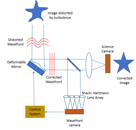
Figure 1 The Classic Adaptive Optics Closed loop approach.
The Classic Adaptive Optics setup uses a beam splitter to divert a wavelength which is not of interest for the main data collection camera and directs it towards a high speed wavefront Sensor camera (EMCCD or sCMOS) see figure 1. A technique known as Shack-Hartmann is used whereby the light from a single point source (typically a single star) is imaged through a series of micro lenses which create an array of spots on the Wavefront camera see figure 2. A computer connected to the Wavefront sensor camera will note that the array of spots are not uniformly spaced, the computer will calculate the appropriate mirror shape which would place these spots in a uniform grid pattern. As the deformable mirror takes on its new shape the spots on the Wavefront sensor will become correctly positioned and at this moment the science camera will receive a corrected image. Atmospheric turbulence will immediately make the spots move, the computer will recalculate a new mirror shape and the process will continually repeat at a rate of about 1000 images per second.
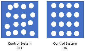
Image at Wavefront sensor camera with Shack – Hartmann closed loop system turned off and on.
To achieve these corrections the beamsplitter, wavefront camera, deformable mirror and computer system must be configured in a low-latency / rapid feedback (closed loop) configuration. When used together at high speed, typically about 500fps to 1 kHz, the atmospheric distortions can be minimised and a corrected wave front now produces a High Resolution Image directed onto a 2nd Imaging Camera. it is common to refer to the Wavefront sensing camera as a Technical Camera and the 2nd imaging camera as a Scientific Camera.
Whilst the adaptive optics system and associated Wavefront camera are operating at approximately 1000 images per second, the science camera can acquire amazingly crisp long exposure images takes over multiple minutes.
For more detail on how Adaptive Optic setups are used please see our technical note on Astronomical applications of Adaptive Optics.

