Published: 10 Feb 2021 · Last updated: 09 Nov 2023
Dragonfly®'s confocal dual spinning disk technology provides an ideal platform for high speed, high SNR imaging, with low bleach rate and phototoxicity. Dragonfly offers:
Isolated detection channel with extremely low background - optimal for EMCCD and sCMOS technology
Efficient illumination coupling via a microlens array (~60%)
Low peak power by parallel illumination of ~100's scanning laser points
Efficient parallel detection with highest QE - 90% peak
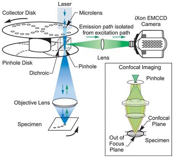
Confocal roughly translates as ‘having the same focus’ and light is collected from the same focal position by spatial filtering i.e. a pinhole. A pinhole can be used to spatially resolve light from a particular depth or plane in an object.
As can be seen from the diagram above, only light (denoted by green) from the right plane passes through the pinhole. Light from the plane above the imaged plane (denoted in red) is focussed above the pinhole so most of the light fails to pass through the pinhole. Conversely light from the plane below the imaged plane (denoted in yellow) focuses before the pinhole and fails to pass through the pinhole. Therefore only light from one plane is in focus to pass through the pinhole or as the name suggest ‘confocal’. A similar principal applies to a pinhole camera which uses a pinhole to obtain crisp images without a lens.
An image of a point of light has a finite size and whether it originates from the image of a star through a telescope or the image of a nanodot through a microscope the image of the point will have a characteristic shape created by diffraction effects called an Airy diffraction pattern. The central spot in the diffraction pattern of the image is called an Airy disk after George Airy the scientist who described the theory behind the diffraction pattern which gives rise to the effect. The diffraction pattern has a large central spot surrounded by several fine diffraction rings like the rings around the bull’s-eye of a target. The diameter of the Airy disk is approximately equal to 1.22 times the wavelength of light divided by the numerical aperture of the imaging optics. In confocal microscopy the size of the pinhole should be matched to the size of the Airy disk as this will allow the most light through ~95% while preserving the best confocal images.
In a conventional widefield microscope, the entire specimen is bathed in light from a mercury or xenon source, and the image can be viewed directly by eye or projected onto an image capture device. The light from different planes in an object overlaps in the camera to obscure the image. In contrast, the method of image formation in a confocal microscope is fundamentally different. Illumination is achieved by scanning one or more focused beams of light, usually from a laser or arc- discharge source, across the specimen. LSCM depend on a small spot of high intensity with a known wavelength. Although other techniques are possible, laser light is ideally suited for this demand. The point of illumination is brought to focus in the specimen by the objective lens, and laterally scanned using some form of scanning device under computer control. The sequences of points of light from the specimen are detected by a photomultiplier tube (PMT) through a pinhole, and the output from the PMT is assembled into an image and displayed by the computer.
Although unstained specimens can be viewed using light reflected back from the specimen, they usually are labelled with one or more fluorescent probes. When using multiple fluorescent probes or fluorophores they can be individually excited and detected by using multiple laser lines. LSCM when used with high numerical aperture lenses, have an inherent speed limitation in fluorescence. This arises because of a limitation in the amount of light that can be obtained from the small volume of fluorophore contained within the focus of the scanned beam (about a cubic micron). At moderate levels of excitation, the amount of light emitted will be proportional to the intensity of the incident excitation. However, fluorophore excited states have significant lifetimes (in the order of a few nanosecond). Therefore, as the level of excitation is increased, the situation eventually arises when most of the fluorophore molecules are pumped up to their excited state and the ground state becomes depleted. At this stage the fluorophore is saturated and no more signal may be obtained from it by increasing the flux of the excitation source.
Most commercial scanning beam confocal microscopes have laser excitation sources that give around 10 mW in the major spectral lines. When the spectral line is near the excitation peak of the fluorophore being used (e.g. the 488nm argon line and fluorescein) and a high numerical aperture lens is used (>1.0 NA) this power level will cause saturation giving image degradation. Better images will be obtained by reducing the power by a factor of 10 or 100. This limits the speed which an image with a given signal-to-noise ratio can be acquired. Typically, about 5 -10 seconds of integration is required with an average immunofluorescence preparation.
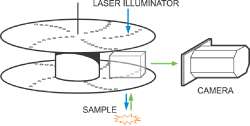
The speed limitations imposed by LSCM can be overcome by parallelism. An array of beams can be used in parallel either by using either a line of pinholes or an array of pinholes. Multiple-beam confocal microscopes have a higher speed potential than point-scanners because their inherent parallelism avoids fluorophore saturation enabling higher levels of excitation to be used. Multiple-beam confocal systems are likely to find applications in areas such as the imaging of high speed intracellular events such as the visualization of calcium ion transients. The principal of generating images using an array of pinholes was first proposed in 1883 by German Physicist Paul Nipkow. The array of scanning pinholes is called a Nipkow disc after him and they formed the basis of the first television cameras.
The diagram above shows the heart of a practical Nipkow spinning disc system. A laser is used to illuminate the sample and this is focused through a pinhole as well to ensure the laser only illuminates the region and plane of the sample that is to be imaged. Typically the light from the sample is separated from the illumination by filters, especially if we are using fluorescent imaging. The light from the sample is re-imaged through the pinhole to reject out of plane light which will obscure the image and directed towards an imaging system such as a camera. In the Andor implementation of the spinning disk, the laser light which enters parallel is focused through an array of micro-lens for each pinhole to ensure good coupling efficiency. The patented array of microlens allows very efficient coupling of the laser to the pinholes which reduces the power of laser needed to achieve good confocal imagines. See the diagram above for the internal layout of the Dragonfly Spinning Disk.
Confocal microscopy, multiphoton excitation, and deconvolution techniques enable observation of the details within thick specimens by a process known as optical sectioning, without the artifacts that accompany specimen preparation by physical sectioning. Specimens having a moderate degree of thickness (5 to 15 microns) will produce dramatically improved images with confocal, multiphoton, or deconvolution techniques. The thickest specimens (20 microns and above) will suffer from a tremendous amount of extraneous light originating in out-of- focus regions, and are probably best-imaged using confocal or multiphoton techniques. In a practical arrangement of the optical sectioning the sample is typically placed on a Piezo controlled stage which allows very fine movement in the vertical direction of the sample. By taking successive images at different optical depths a three-dimensional image of a living cell can be obtained.