Profile Control for Slanted Etching
Introduction
The need for forming slanted gratings for applications such as combiners for AR headsets has seen a recent surge. Ion beam etching technology is one of the best suited techniques to enable the grating design required for these applications. Ion beam directionality in conjunction with variable incident beam angle via platen angle setting enables profile control and feature shaping during nanopatterning.
Ion beam expertise is critical to deliver the manufacturing tolerance required for these gratings. Oxford Instruments Plasma Technology has developed a technology to allow optical designers to build high quality gratings for masters. Our solution delivers a large uniform processing area over 200 mm wafers for angles from 0° to 55°. In this paper, we share our experience in tuning the process for excellent shape control.
Process Tuning for Slanted Gratings
Unique ion beam capability allows materials to be etched without rotation, at a fixed platen angle. This technique can be applied to create slanted gratings as well as slanted waveguide facets. Figures 1a and 1b show schematic drawings of before and after etch process and the actual process set up with platen angle set to 35°. This can be done for shallow or deep etched gratings; the typical mask is photoresist or a metal such as Cr or Al. The angle targeted is usually between 35° and 55°.
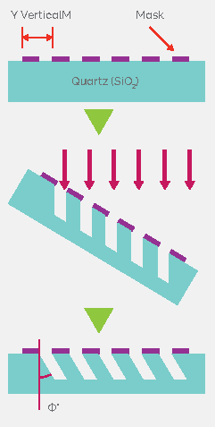
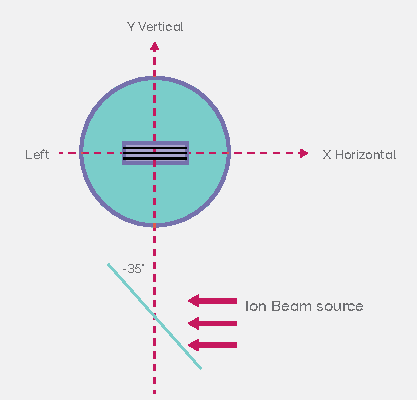
Fig. 1 — Figure 1a: Fixed angle etch process flow showing before and after etch schematic. Figure 1b: Process set up with platen angle set to -35° and ion beam source orientation.
In ion beam etching, the platen angle defines the angle of incidence of the ions. Further process adjustments are achieved using parameters such as the beam current, the beam voltage, accelerator voltage and source gas flows. When etching slanted features, critical parameters include the fill factor, the CD variation and the etching depth. To meet these requirements, the thickness of the mask should be carefully selected as the selectivity can be limited in a physical etch. However, it is not recommended to use an excessively thick mask as the aspect ratio might affect the etch profile quality due to shadowing depending on the platen angle.
When etching slanted features, it is also critical to have control over sidewall angles and how parallel the sidewalls are. In order to achieve equal depth either side of the trench, we recommend using a chemical process rather than a purely physical process. Chemical by-products will be removed easily in tight corners naturally created because of the slanted profile. Typically, a mixture of Ar/CHF3 for SiO2 and Ar with SF6 or Cl2 can be used for Si.
The potency of the chemical and physical side of the etch is also tightly linked with the beam current (IB), and beam voltage (VB). The higher the beam current, the more dominant the chemical side will be; whilst the higher the beam voltage, the more dominant the physical side will be.
The beam voltage drives the directionality of the etch whilst the chemical side provides the isotropic and necessary material removal required.
Case Study: Etching Slanted Gratings on SiO2 Substrate
Figure 2a shows SiO2 etched vertically while Figure 2b shows SiO2 etched at a fixed angle, both with a pure Argon process. The bottom of the etch is perpendicular to the incident beam direction but the sidewalls are sloped, affecting the CD.
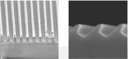
Fig. 2 — Figure 2a: SiO2 etched vertically. Figure 2b: SiO2 etch at a fixed angle with Ar only.Adding more CHF3 with a high beam current will tend to make the balance between the physical and chemical part tip towards the chemical side and give a more isotropic etch, see Figure 3a. Depending on the pitch, here under 500 nm, and the desired angle, one can also end up with some shadowing from the mask itself that will affect the sidewalls shape, see Figures 3b and 3c with a strong shadowing effect.
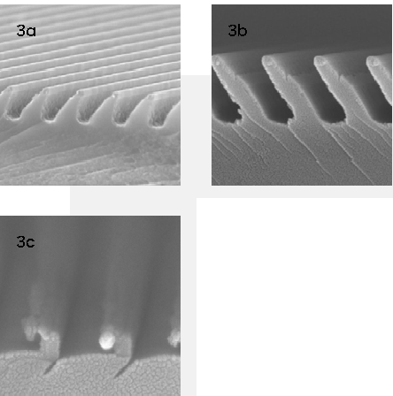
Fig. 3 — Figure 3a: SiO2 over-chemically etched from mask. Figure 3b: Shadowing effect from mask. Figure 3c: Strong shadowing effect.When the right balance between the physical and chemical part of the etching is found, well defined slanted angles and profiles can be obtained, see Figures 4a and 4b below for shallow etched process.
Static etch examples 1 and 2 used Cr and Al mask, respectively. Table 1 below gives a summary of the SiO2, Cr and Al etch rate as well as their depth and selectivity. Note that the mask pitch was 400 nm.
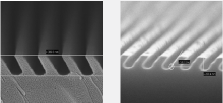
Fig. 4 — Figure 4a: Static SiO2 etched example 1. Figure 4b: Static SiO2 etched example 2.
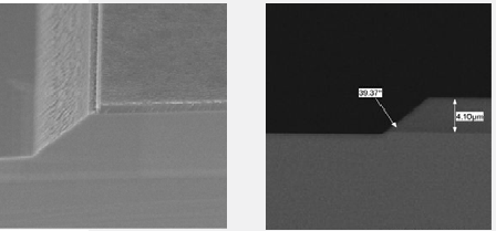
Figure 5: Deep static SiO2 etched SEMs from different samples.
| Cr Mask | Al mask |
| SiO2 etch rate [nm/min] | 24 | 27 |
| Cr etch rate [nm/min] | 2 | NA |
| Al etch rate [nm/min] | NA | 5 |
| Selectivity to mask | 12.5 | 5.4 |
| Etched depth | 400 | 264 |
Table 1: Relative etch rate and selectivity for shallow etch examples with Cr and Al mask.
This can be done with a much larger mask pitch, such as 30 µm, with deeper etch. See Figure 5 for SEMs of such an example. A photoresist mask has been used in this case.
The corresponding etch rate for the static deep etch example described above of SiO2 and photoresist is 40 and 4 nm/min. This gives a selectivity of SiO2 to the mask equal to 10 for a total vertical depth of 4.1 µm.
Conclusion
Process results using Reactive Ion Beam Etching was reported. With its ability to independently set the various beam parameters such as beam current density, beam energy, gas flow, different gas mixture flows, ion beam technology is a very versatile technique that enables superior control of sidewall angle and smoothness. OIPT expertise in slanted etching has enabled careful process tuning to balance the physical and chemical environments to achieve the desired process results shown above.

